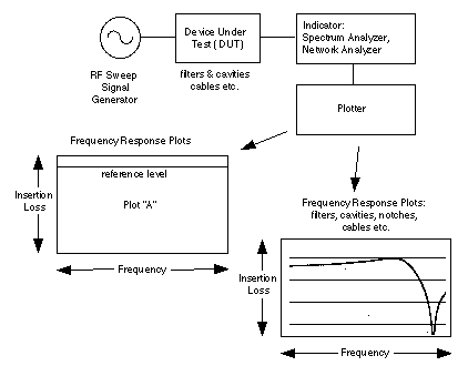
Test Set-up
The "Swept Frequency Response Test Setup" page is included to help understand the principle by which most RF measurements and alignments are made, especially those for filters and duplexers. Operation is straight forward, an RF (Radio Frequency) signal from as signal generator is observed on an indicator, usually a spectrum analyzer or network analyzer. "DUT"s (Devices Under Test) are merely inserted between the generator and the indicator and the DUT is tuned to obtain the desired response which is then plotted. Plots are usually measured in dB (decibels) for loss or gain and frequency is measured in MegaHertz (MHz). These plots are used to indicate the performance of a device so comparisons and differences can be easily recognized. This helps to determine solutions to problems. The more you know about your system the better able you are to solve problems that may arise, especially interference problems. By correctly configuring or designing your system you can virtually eliminate all interference problems. The following discussion will tell you why and how.

This scheme is used to measure the performance of RF (Radio Frequency) components. It provides you with all of the information that is required to evaluate, trouble-shoot and tune most components of a typical repeater system. The plots are usually displayed in dB (decibels) and MHz (MegaHertz). Usually a device is inserted between the generator and the indicator and its performance is then compared to the reference condition.