
updated May 2004
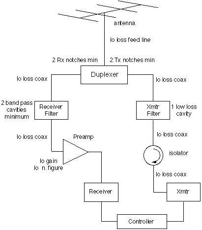
Typical block diagram of a well designed repeater system
The "Swept Frequency Response Test Setup" page is included to help understand the principle by which most RF measurements and alignments are made, especially those for filters and duplexers.
Duplexers:
Duplexers are merely a three port version of a resonant devices that allows simultaneous receiving and transmitting on a common antenna but at two separate frequencies. The separation of the two frequencies is commonly referred to the "split" and is usually determined by the practical physical limit of construction of the components used to make the duplexer.
Duplexers are usually made from "notch" type resonators to provide the attenuation necessary to allow this simultaneous transmitting and receiving. They can also be made using regular band pass filters provided there is adequate skirt rejection. This is usually not the case at lower frequencies because the receive and transmit splits are so small, <1/2%.
Generally the bigger the diameter the better when it comes to filtering as the losses will be lower (not always) and the quality of the resonator will be better.
Many people believe their duplexer will actually provide some sort of filtering for their receiver since they are using "cavities" especially since they are called "band pass band reject" or some other sort of misleading terminology. The term cavities is really incorrect but it seems impossible to get people to change. Let's call them "resonators" out of convenience since we all know what that means. A true cavity is an empty box or cylinder which exhibits some resonances which are determined by its physical size. The term "cavity" used by most communications people is really a coaxial transmission line of 70 Ohm impedance and is typically one quarter wavelength long.
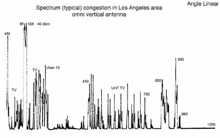
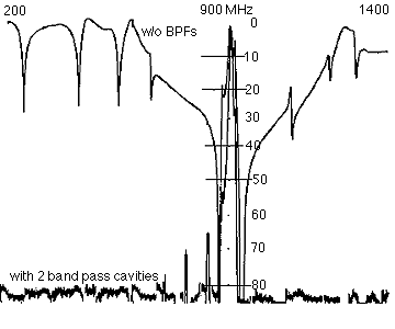
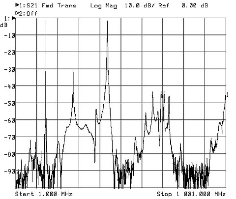
All the duplexer will really do is get rid of your transmitter and anyone else who is very close to your transmit frequency. See the "150 MHz duplexer" plots to get a realistic idea of how your duplexer really looks to the rest of the world and what your poor receiver has to tolerate. Now compare that plot to the typical Los Angeles spectrum plot. It is pretty obvious there is a need for additional filtering on the receiver and transmitter ports of the average duplexer. Also see the typical plot of a PHEMT preamplifier to see that there is virtually no filtering in it and that it has gain way outside the designed operating passband.
Interference Data Collection:
The best way to assure interference free operation of your repeater is to prove what interference you need to eliminate. This interference information or data can be obtained with a spectrum analyzer. Measure all signals from at least 50 MHz to 1000 MHz and record all signals greater than -50 dbm. The objective of the filtering is to reduce all out of band signals to below -50 dbm. With the correct amount of filtering you can do this and have virtually interference free repeater system. The minimum filtering we recommend is two (2) band pass resonators on the receive port of any duplexer regardless of who makes it or what fancy name it has. They all need band pass filtering to get the out of band unwanted signals down to a tolerable level. Some locations may require three (3) resonators on the receive port of the duplexer to survive; it all depends on your location and circumstances. Remember: no guessing.......hoping you won't have any interference won't work either...prove everything!
Notches:
Duplexers are usually assembled from notches which give maximum attenuation at only one frequency and have minimum attenuation at only one pass frequency. The bandwidth of these characteristics can vary but generally they are a few hundred kiloHertz at most.
See the "Typical Notch Configurations" page for the physical implementation and performance comparisons of the two main types of notches in use today. The "Deep Notch" type are used in duplexers since they provide the greatest attenuation at the notch frequency. The "Narrow Notch" is used to compliment band pass filters; to help "steepen up" the skirts of a filter.
By combining two deep notches in series, the characteristics of each will add and the result will be twice the attenuation at the notch frequency and twice the attenuation at the pass frequency as well. Usually 90 to 100 dB of attenuation is adequate to eliminate all affects of the transmitter on the receiver, overload and noise, etc. In some high power cases (>100 Watts) and additional 10 or 20 dB of rejection (notch) may be required.
By combining two pairs of notches, one pair for receive and one pair for transmit, one type of duplexer can be made. Alignment is simple: separate all cans and individually tune (and prove) them, then hook them back up without retuning them. If they were designed correctly and the cable lengths are correct the performance will not change when things are recombined. The depth of the notches and the insertion losses will add correctly and most importantly, the SWR or return loss will not change on the alignment frequency.
Receiver Filtering:
Take a look at the "150 MHz six 'cavity' duplexer" and typical "900 MHz" plots to see the where receiver problems can arise. These are a result of the "notch" approach to designing a duplexer. Most duplexers below 1GHz are of this type. Most of the real RF world can easily pass into the front of your receiver virtually unattenuated, see the typical spectrum plot. There ia an average of only a few dB attenuation away (out of band) from the operating frequency. If you are using a preamplifier then there is no protection for your receiver whatsoever from being overloaded by signals even several hundred MegaHertz away. They can even be on distant mountain tops and still be causing you interference. The inclusion of a two or more of band pass resonators on the receive port of the duplexer will eliminate virtually all of the interference from out of band signals. A low pass filter on the antenna port would eliminate all higher frequency harmonic responses at a cost of 0.125 db
Transmitter Filtering & Isolators:
Transmitter filtering is required usually not to clean up your output but to keep others from getting into your transmitter amplifier where they can mix and produce unwanted signals and get re-radiated from your antenna. If your duplexer passes your signal to the antenna then it will allow others to get back in. The response of the 150 MHz six can duplexer also applies to the transmitter port as well as the receiver port. It can be seen that virtually any signal can pass only slightly attenuated into your transmitter. Even if your transmitter has a 60 dB down second harmonic low pass filter it can be susceptible to signals below the cutoff frequency of the low pass filter.
The isolator, a circulator with a dummy load, on the transmitter is like an RF diode in that it exhibits directional characteristics. Your transmitter signal can go to the antenna but signals from the antenna can't get back to your transmitter. However, this is the real world.........Nothing is perfect, including isolators. They have only so much "directivity" that is, the ratio of forward loss to backward loss usually expressed in dB. 20 to 25 dB is normal for single stage isolators. Multiple isolators are usually used for transmitter combiners since their directivity will add increasing this isolation.
Isolators are tuned devices and only operate over a certain bandwidth. They keep in-band signals from getting into your transmitter. Outside of this operating bandwidth they look like a 50 Ohm transmission line and once again allow out of band signals into your transmitter amplifier. The addition of a low loss band pass filter after the isolator will complement the directivity passband of the isolator and your transmitter from out of band signals while reducing some of the harmonics produced by your transmitter amplifier and the isolator. It would be better if no harmonics came out of your power amplifier.
Preamplifiers:
Preamplifiers can be a major source of problems. Many manufacturers produce amplifiers which have entirely too much gain. This excessive gain can overload the typically low dynamic range of most receiver front ends. Most receivers use low current bipolar or dual gate MOSFET front end preamplifiers and mixers. The rule is " the farther you get into the receiver the higher the required signal handling capability of each stage". So be kind to your receiver and don't put a 40 dB gain preamplifier in front of it. For those of us who live in the city we have too much man made noise already and in many cases you are only going to make it worse by including a high gain preamplifier. Keep the gain down to 15 dB or so and some of your problems will be prevented. If you need to reduce the gain, use a 3 or 6 db 50 Ohm attenuator after the preamplifier, not before. Attenuators are usually 50 Ohms, require no DC power, won't oscillate and are predictable in performance.
Coaxial Cables:
Now that you have gone to all of this work to get your system filtered and clean don't throw some of your efforts away by using interconnect cabling that reduce its performance. Double shielded cable is a must. Low insertion loss is also important. Look at the specifications on most cheap cable today and you will find it has effective braid shielding of something less than 98%. What about the 2% left over? It's all holes......... That's where the problem occurs, it leaks going in and out. Double braid or foil with braid is the minimum that should be used for any interconnect cable. While you are at it never use BNC connectors since they also leak and aren't mechanically very strong. Stick with connectors which are rugged and have a good 50 Ohm impedance. Not PL-259s!